US12460888 - Suppressor with gas cross flow and reduced back pressure
The patent describes a firearm suppressor featuring a tubular housing and a baffle stack designed to manage gas flow, including flow-directing structures such as diverging and converging vanes. This innovative design aims to reduce back pressure while effectively directing gas flow across the bore axis for improved performance.
Claim 1
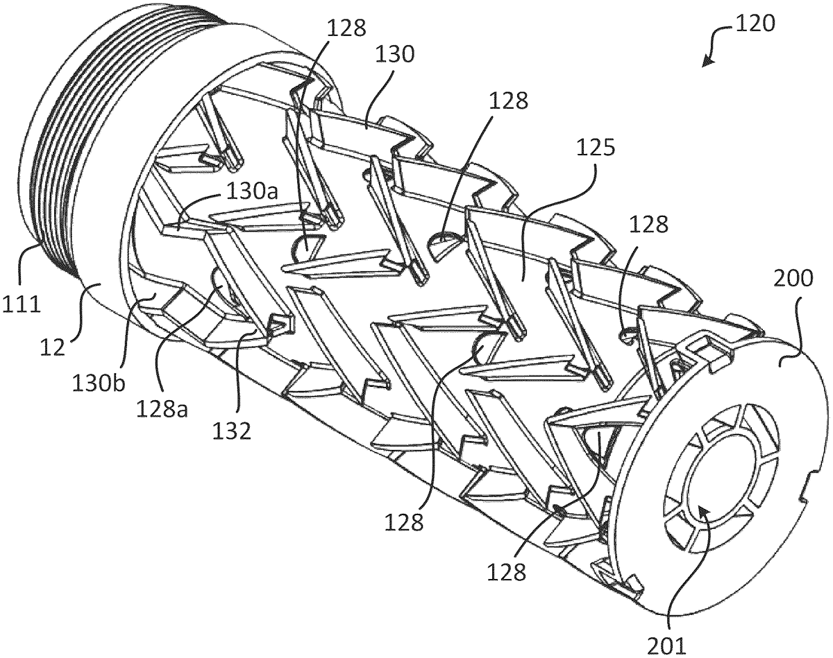
1 . A suppressor comprising: a tubular housing extending along a bore axis from a proximal end to a distal end; a baffle stack within the tubular housing and extending along the bore axis from a proximal baffle stack end to a distal baffle stack end, the baffle stack comprising a tubular baffle wall with a plurality of baffle structures connected to an inside of the tubular baffle wall, and individual baffle structures tapering proximally to a central opening on the bore axis, wherein the suppressor defines an inner volume inside of the tubular baffle wall, and an outer volume between the tubular baffle wall and the tubular housing; flow-directing structures in the outer volume, the flow-directing structures including pairs of diverging vanes and pairs of converging vanes with respect to gases flowing distally through the suppressor; and a conduit extending between and connecting adjacent baffle structures, wherein the conduit defines a gas flow pathway in a radially outer portion of the inner volume and the conduit defines an opening located between the adjacent baffle structures and configured to direct gas flow across the bore axis. a tubular housing extending along a bore axis from a proximal end to a distal end; a baffle stack within the tubular housing and extending along the bore axis from a proximal baffle stack end to a distal baffle stack end, the baffle stack comprising a tubular baffle wall with a plurality of baffle structures connected to an inside of the tubular baffle wall, and individual baffle structures tapering proximally to a central opening on the bore axis, wherein the suppressor defines an inner volume inside of the tubular baffle wall, and an outer volume between the tubular baffle wall and the tubular housing; flow-directing structures in the outer volume, the flow-directing structures including pairs of diverging vanes and pairs of converging vanes with respect to gases flowing distally through the suppressor; and a conduit extending between and connecting adjacent baffle structures, wherein the conduit defines a gas flow pathway in a radially outer portion of the inner volume and the conduit defines an opening located between the adjacent baffle structures and configured to direct gas flow across the bore axis.
Google Patents
https://patents.google.com/patent/US12460888
USPTO PDF
https://image-ppubs.uspto.gov/dirsearch-public/print/downloadPdf/12460888