US12460908 - Hunting game tracking system
The patent describes a hunting game tracking system that incorporates a trackable broadhead assembly with a releasable tracker housing designed to be ejected into an injured game animal upon impact. This system utilizes a transmitter that wirelessly communicates with a GPS unit to facilitate the tracking of the animal’s location after the arrow has been shot.
Claim 1
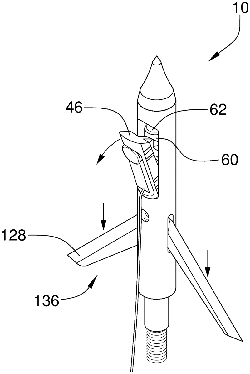
1 . A trackable broadhead assembly comprising: an arrowhead having an aft end, a tip end, and a ferrule extending between the aft end and the tip end; a tracker being releasably coupled to the arrowhead wherein the tracker is configured to be released from the arrowhead when the arrowhead moves through an animal, the tracker including: a tracker housing having a front side, a back side, and an upper end, the upper end being angled to extend outwardly from the front side and downwardly toward the back side; a transmitter being coupled to the tracker housing, the transmitter being configured to wirelessly communicate with one of a global positioning system unit and a radio frequency receiver unit wherein the transmitter is configured to identify a geographic location of the tracker housing and wherein the tracker is configured to facilitate locating the animal using the geographic location of the tracker housing; an ejector being movably positioned within the ferrule, the ejector being operably coupled to the tracker wherein movement of the ejector within the ferrule releases the tracker from the arrowhead, the ejector including: an ejector top end being positioned adjacent to the tip end of the arrowhead; and a cutout being positioned adjacent to the ejector top end, the cutout having a shape being complementary to a shape of the tracker housing wherein the tracker housing is positionable within the cutout, the cutout including: a sloped upper wall being angled to complement the upper end of the tracker housing wherein the sloped upper wall is in contact with the upper end of the tracker housing and wherein the sloped upper wall is configured to slide downwardly against the upper end of the tracker housing to urge the tracker housing outwardly from the arrowhead into the animal. an arrowhead having an aft end, a tip end, and a ferrule extending between the aft end and the tip end; a tracker being releasably coupled to the arrowhead wherein the tracker is configured to be released from the arrowhead when the arrowhead moves through an animal, the tracker including: a tracker housing having a front side, a back side, and an upper end, the upper end being angled to extend outwardly from the front side and downwardly toward the back side; a transmitter being coupled to the tracker housing, the transmitter being configured to wirelessly communicate with one of a global positioning system unit and a radio frequency receiver unit wherein the transmitter is configured to identify a geographic location of the tracker housing and wherein the tracker is configured to facilitate locating the animal using the geographic location of the tracker housing; a tracker housing having a front side, a back side, and an upper end, the upper end being angled to extend outwardly from the front side and downwardly toward the back side; a transmitter being coupled to the tracker housing, the transmitter being configured to wirelessly communicate with one of a global positioning system unit and a radio frequency receiver unit wherein the transmitter is configured to identify a geographic location of the tracker housing and wherein the tracker is configured to facilitate locating the animal using the geographic location of the tracker housing; an ejector being movably positioned within the ferrule, the ejector being operably coupled to the tracker wherein movement of the ejector within the ferrule releases the tracker from the arrowhead, the ejector including: an ejector top end being positioned adjacent to the tip end of the arrowhead; and a cutout being positioned adjacent to the ejector top end, the cutout having a shape being complementary to a shape of the tracker housing wherein the tracker housing is positionable within the cutout, the cutout including: a sloped upper wall being angled to complement the upper end of the tracker housing wherein the sloped upper wall is in contact with the upper end of the tracker housing and wherein the sloped upper wall is configured to slide downwardly against the upper end of the tracker housing to urge the tracker housing outwardly from the arrowhead into the animal. an ejector top end being positioned adjacent to the tip end of the arrowhead; and a cutout being positioned adjacent to the ejector top end, the cutout having a shape being complementary to a shape of the tracker housing wherein the tracker housing is positionable within the cutout, the cutout including: a sloped upper wall being angled to complement the upper end of the tracker housing wherein the sloped upper wall is in contact with the upper end of the tracker housing and wherein the sloped upper wall is configured to slide downwardly against the upper end of the tracker housing to urge the tracker housing outwardly from the arrowhead into the animal. a sloped upper wall being angled to complement the upper end of the tracker housing wherein the sloped upper wall is in contact with the upper end of the tracker housing and wherein the sloped upper wall is configured to slide downwardly against the upper end of the tracker housing to urge the tracker housing outwardly from the arrowhead into the animal.
Google Patents
https://patents.google.com/patent/US12460908
USPTO PDF
https://image-ppubs.uspto.gov/dirsearch-public/print/downloadPdf/12460908