US12476383 - Integrated infrared imaging and passive seeker system for small munitions application
The patent describes an integrated imaging and passive seeker system for guided munitions, featuring an electro-optical infrared (EOIR) imager and a passive direction finding (DF) sensor system housed within a tapered conical chassis. The system utilizes log periodic array (LPA) antenna elements to detect signals of interest in the ultra-wide band frequency range, enabling target identification and guidance for improved accuracy.
Claim 1
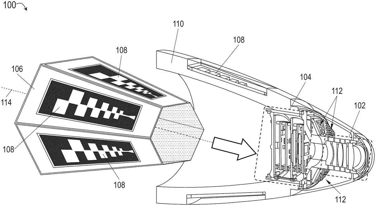
1 . An integrated imaging and passive seeker system for a guided munition, comprising: an electro-optical infrared (EOIR) imaging system mountable within a nosecone of a guided munition, the EOIR imaging system comprising: at least one optical element disposed proximate to a forward radome, the forward radome corresponding to a tip of the nosecone; and at least one EOIR imager disposed within an electronics stack mountable behind the at least one optical element, the EOIR imager configured to sense image data associated with at least one target via the at least one optical element; and a passive direction finding (DF) sensor system mountable within the nosecone and comprising: a tapered conical ground chassis having an N-sided polygonal cross section with respect to its longitudinal axis, where N is an integer not less than 3; a plurality of N log periodic array (LPA) antenna elements, each LPA antenna element disposed on one of the N sides of the ground chassis proximate to the nosecone, the plurality of LPA antenna elements electromagnetically shielded from the EOIR imaging system by the ground chassis, each LPA antenna element configured to: produce a detection input by transmitting and receiving RF energy associated with at least one frequency band in the ultra-wide band (UWB) frequency range not less than 2 GHZ and not more than 18 GHZ; and at least one RF integrated circuit (RFIC) disposed within the electronics stack and operatively coupled to the plurality of N LPA antenna elements via at least one dedicated RF channel, the at least one RFIC configured for: receiving, via the at least one dedicated RF channel, the detection input from the N LPA antenna elements; identifying, based on the detection input, one or more signals of interest (SoI) associated with the at least one target, each SoI associated with a frequency sub-band within the UWB range; determining directional data associated to at least one selected SoI of the one or more SoI, based on the sub-band associated with the selected SoI; and providing the directional data to a guidance system of the munition. an electro-optical infrared (EOIR) imaging system mountable within a nosecone of a guided munition, the EOIR imaging system comprising: at least one optical element disposed proximate to a forward radome, the forward radome corresponding to a tip of the nosecone; and at least one EOIR imager disposed within an electronics stack mountable behind the at least one optical element, the EOIR imager configured to sense image data associated with at least one target via the at least one optical element; and a passive direction finding (DF) sensor system mountable within the nosecone and comprising: a tapered conical ground chassis having an N-sided polygonal cross section with respect to its longitudinal axis, where N is an integer not less than 3; a plurality of N log periodic array (LPA) antenna elements, each LPA antenna element disposed on one of the N sides of the ground chassis proximate to the nosecone, the plurality of LPA antenna elements electromagnetically shielded from the EOIR imaging system by the ground chassis, each LPA antenna element configured to: produce a detection input by transmitting and receiving RF energy associated with at least one frequency band in the ultra-wide band (UWB) frequency range not less than 2 GHZ and not more than 18 GHZ; and at least one RF integrated circuit (RFIC) disposed within the electronics stack and operatively coupled to the plurality of N LPA antenna elements via at least one dedicated RF channel, the at least one RFIC configured for: receiving, via the at least one dedicated RF channel, the detection input from the N LPA antenna elements; identifying, based on the detection input, one or more signals of interest (SoI) associated with the at least one target, each SoI associated with a frequency sub-band within the UWB range; determining directional data associated to at least one selected SoI of the one or more SoI, based on the sub-band associated with the selected SoI; and providing the directional data to a guidance system of the munition. a tapered conical ground chassis having an N-sided polygonal cross section with respect to its longitudinal axis, where N is an integer not less than 3; a plurality of N log periodic array (LPA) antenna elements, each LPA antenna element disposed on one of the N sides of the ground chassis proximate to the nosecone, the plurality of LPA antenna elements electromagnetically shielded from the EOIR imaging system by the ground chassis, each LPA antenna element configured to: produce a detection input by transmitting and receiving RF energy associated with at least one frequency band in the ultra-wide band (UWB) frequency range not less than 2 GHZ and not more than 18 GHZ; produce a detection input by transmitting and receiving RF energy associated with at least one frequency band in the ultra-wide band (UWB) frequency range not less than 2 GHZ and not more than 18 GHZ; and at least one RF integrated circuit (RFIC) disposed within the electronics stack and operatively coupled to the plurality of N LPA antenna elements via at least one dedicated RF channel, the at least one RFIC configured for: receiving, via the at least one dedicated RF channel, the detection input from the N LPA antenna elements; identifying, based on the detection input, one or more signals of interest (SoI) associated with the at least one target, each SoI associated with a frequency sub-band within the UWB range; determining directional data associated to at least one selected SoI of the one or more SoI, based on the sub-band associated with the selected SoI; and providing the directional data to a guidance system of the munition. receiving, via the at least one dedicated RF channel, the detection input from the N LPA antenna elements; identifying, based on the detection input, one or more signals of interest (SoI) associated with the at least one target, each SoI associated with a frequency sub-band within the UWB range; determining directional data associated to at least one selected SoI of the one or more SoI, based on the sub-band associated with the selected SoI; and providing the directional data to a guidance system of the munition.
Google Patents
https://patents.google.com/patent/US12476383
USPTO PDF
https://image-ppubs.uspto.gov/dirsearch-public/print/downloadPdf/12476383