US12492880 - Accessory mount
The patent describes a multi-position accessory mount designed for attachment to rail interface systems like the Picatinny rail, featuring a spring-loaded push-button recoil lug and an adjustment knob for quick repositioning and secure attachment. This innovative design allows for easy adjustment of sliding tension and facilitates the attachment and removal of accessories without needing to slide the mount off the rail.
Claim 1
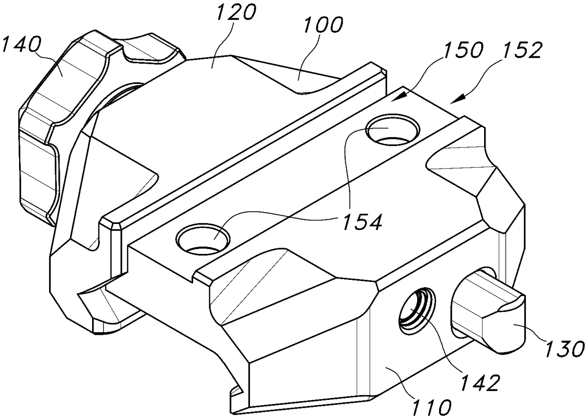
1 . An accessory mount configured for attachment to a rail interface system, the accessory mount comprising: a base comprising a receiving groove; a clamp comprising a receiving groove; a push-button recoil lug comprising an actuating arm, with an actuation button on one end and a recoil lug on the opposite end; and an adjustment knob; wherein: a channel is defined between the receiving groove of the base and the receiving groove of the clamp; the clamp is connected to the base by a threaded shank attached to the adjustment knob; rotation of the adjustment knob causes the clamp to move relative to the base, thereby selectively varying a width of the channel; and the push-button recoil lug is slidably positioned within a guide groove in the base and configured to removably position the recoil lug in the channel. a base comprising a receiving groove; a clamp comprising a receiving groove; a push-button recoil lug comprising an actuating arm, with an actuation button on one end and a recoil lug on the opposite end; and an adjustment knob; wherein: a channel is defined between the receiving groove of the base and the receiving groove of the clamp; the clamp is connected to the base by a threaded shank attached to the adjustment knob; rotation of the adjustment knob causes the clamp to move relative to the base, thereby selectively varying a width of the channel; and the push-button recoil lug is slidably positioned within a guide groove in the base and configured to removably position the recoil lug in the channel.
Google Patents
https://patents.google.com/patent/US12492880
USPTO PDF
https://image-ppubs.uspto.gov/dirsearch-public/print/downloadPdf/12492880