US12504252 - Rapid repeating device
The patent describes a rapid repeating device that integrates a main body with an arrow portion, shooting portion, and trigger unit, allowing for sequential firing of arrows through a control component that interacts with a trigger mechanism. The device features a control handle unit that pivots to switch between loading and shooting modes, enabling arrows to be loaded and fired efficiently.
Claim 1
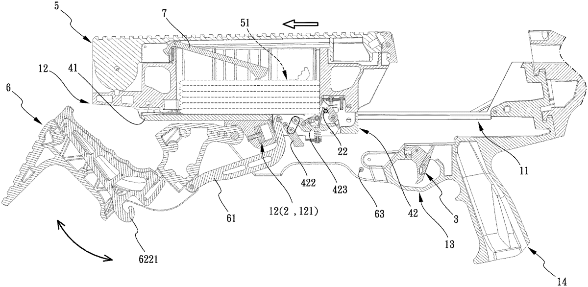
1 . A rapid repeating device, comprising: a main body, having an arrow portion on the top, a shooting portion equipped with a bowstring component, and a trigger portion at the bottom and provided with a trigger unit; a control component, disposed on the arrow portion of the main body, and partially located inside the main body and partially exposed outside the arrow portion; wherein when the control component moves toward the shooting portion, the control component is away from the trigger unit, and when the control component moves away from the shooting portion, the control component movably abuts against the trigger unit; an arrow box, disposed on the top of the main body; wherein a plurality of arrows are disposed in the arrow box and one by one fall into the control component that is partially exposed outside the arrow portion; and a control handle unit, having one end pivotally disposed on the main body and located below the arrow portion; wherein, the control handle unit is pivotally assembled with the control component, wherein a loading mode is formed when the control handle unit is pivoted relative to the main body and moves the control component toward the shooting portion; wherein a shooting mode is formed when the control handle unit is pivoted to the direction opposite to the shooting portion and moves the control component back; an arrow sliding base mounted on the arrow portion, and having an installation port corresponding to one end of a brake unit; wherein the brake unit is partially assembled on the installation port, and the control handle unit is partially assembled to the brake unit; wherein the brake unit is partially abutted against the trigger unit before the brake unit moves toward the shooting portion; wherein the arrow sliding base is recessed with an arrow groove corresponding to the arrow box, so that the plurality of arrows fall into the arrow groove one by one; the brake unit includes a housing, a resisting block, a movable block and a string buckle base; wherein the housing forms an accommodating space inside, one end of the resisting block is pivotally assembled in the accommodating space and the other end of the resisting block resists the trigger unit during the shooting mode; wherein the movable block is pivotally disposed in the accommodating space, and a linking piece is fittingly engaged between the resisting block and the movable block; wherein part of the string buckle base is pivotally disposed in the accommodating space and the other part of the string buckle base protrudes from the installation port and movably restrict and release the bowstring component; wherein the movable block has a blocking portion corresponding to the string buckle base, and the blocking portion is movably abutted against the bottom of the string buckle base; the accommodating space of the housing includes a safety catch, part of the safety catch pivotally assembled in the accommodating space and provided with a limiting hole, and the other part of the safety catch protruding from the installation port; wherein two push rods respectively protrudes/extends from both ends of the part of the safety catch that protrudes from the installation port; wherein the safety catch pivots with the part that located in the accommodating space as the axis point; wherein when the two push rods are near the string buckle base, the end of the safety catch with the limiting hole is away from the movable block, so that the movable block pivots; wherein when the two push rods are away from the string buckle base, one end of the movable block is inserted into the limiting hole to limit pivot movement of the movable block, so that the trigger unit is limited indirectly; wherein through each pivot movement of the control handle unit, the displacement of the control component on the arrow portion is controlled; wherein during the loading mode, the control component does not abut against the trigger unit, and the trigger unit retains the trigger portion; wherein during the shooting mode, the control component moves in the direction opposite to the shooting portion, the control component abuts against the trigger unit, so that it allows the pulling of the trigger unit to drive the control component and release the bowstring component to release the plurality of arrows one by one. a main body, having an arrow portion on the top, a shooting portion equipped with a bowstring component, and a trigger portion at the bottom and provided with a trigger unit; a control component, disposed on the arrow portion of the main body, and partially located inside the main body and partially exposed outside the arrow portion; wherein when the control component moves toward the shooting portion, the control component is away from the trigger unit, and when the control component moves away from the shooting portion, the control component movably abuts against the trigger unit; an arrow box, disposed on the top of the main body; wherein a plurality of arrows are disposed in the arrow box and one by one fall into the control component that is partially exposed outside the arrow portion; and a control handle unit, having one end pivotally disposed on the main body and located below the arrow portion; wherein, the control handle unit is pivotally assembled with the control component, wherein a loading mode is formed when the control handle unit is pivoted relative to the main body and moves the control component toward the shooting portion; wherein a shooting mode is formed when the control handle unit is pivoted to the direction opposite to the shooting portion and moves the control component back; an arrow sliding base mounted on the arrow portion, and having an installation port corresponding to one end of a brake unit; wherein the brake unit is partially assembled on the installation port, and the control handle unit is partially assembled to the brake unit; wherein the brake unit is partially abutted against the trigger unit before the brake unit moves toward the shooting portion; wherein the arrow sliding base is recessed with an arrow groove corresponding to the arrow box, so that the plurality of arrows fall into the arrow groove one by one; the brake unit includes a housing, a resisting block, a movable block and a string buckle base; wherein the housing forms an accommodating space inside, one end of the resisting block is pivotally assembled in the accommodating space and the other end of the resisting block resists the trigger unit during the shooting mode; wherein the movable block is pivotally disposed in the accommodating space, and a linking piece is fittingly engaged between the resisting block and the movable block; wherein part of the string buckle base is pivotally disposed in the accommodating space and the other part of the string buckle base protrudes from the installation port and movably restrict and release the bowstring component; wherein the movable block has a blocking portion corresponding to the string buckle base, and the blocking portion is movably abutted against the bottom of the string buckle base; the accommodating space of the housing includes a safety catch, part of the safety catch pivotally assembled in the accommodating space and provided with a limiting hole, and the other part of the safety catch protruding from the installation port; wherein two push rods respectively protrudes/extends from both ends of the part of the safety catch that protrudes from the installation port; wherein the safety catch pivots with the part that located in the accommodating space as the axis point; wherein when the two push rods are near the string buckle base, the end of the safety catch with the limiting hole is away from the movable block, so that the movable block pivots; wherein when the two push rods are away from the string buckle base, one end of the movable block is inserted into the limiting hole to limit pivot movement of the movable block, so that the trigger unit is limited indirectly; wherein through each pivot movement of the control handle unit, the displacement of the control component on the arrow portion is controlled; wherein during the loading mode, the control component does not abut against the trigger unit, and the trigger unit retains the trigger portion; wherein during the shooting mode, the control component moves in the direction opposite to the shooting portion, the control component abuts against the trigger unit, so that it allows the pulling of the trigger unit to drive the control component and release the bowstring component to release the plurality of arrows one by one.
Google Patents
https://patents.google.com/patent/US12504252
USPTO PDF
https://image-ppubs.uspto.gov/dirsearch-public/print/downloadPdf/12504252