US12504254 - Shell-throwing toy long gun
The patent describes a shell-throwing toy long gun that utilizes a valve assembly to control the flow of high-pressure gas from an air supply unit to the gun mechanism, enabling the ejection of projectiles. The design includes a detachable magazine, a striking unit with a hammer, and a complex air-control system to prevent gas leakage while facilitating projectile launch.
Claim 1
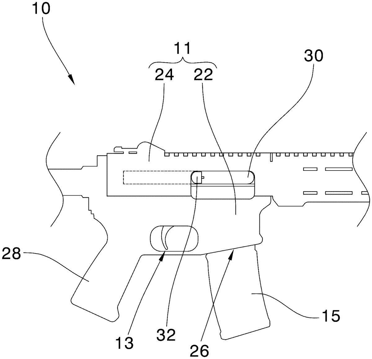
1 . An improved shell-throwing toy long gun, comprising a gun body, an air-control unit, a striking unit, a high-pressure air supply unit, and a magazine; wherein the gun body comprises a detachable lower body and an upper body; the lower body includes a magazine socket and a grip; the upper body has a shell-ejecting port on one side and a gun mechanism inside; the air-control unit and the striking unit are located inside the lower body; the high-pressure air supply unit is located in the grip, configured to output high-pressure gas to the air-control unit; the magazine is detachably inserted into the magazine socket; the air-control unit comprises a lower control module and an upper control module; the high-pressure gas output from the air supply unit can be transmitted to the gun mechanism via the lower and upper control modules, enabling movement of the gun mechanism through high-pressure gas; bullets loaded into the lower body from the magazine can be ejected through the shell-ejecting port by the action of a piston in the gun mechanism; the air supply unit connects to the lower control module; the striking unit connects to one end of the upper control module, within which is installed a valve assembly; one end of the valve assembly corresponds to a hammer in the striking unit; the valve assembly controls whether high-pressure gas flows from the lower control module to the gun mechanism, comprising: the valve assembly comprises a valve stem, an air outlet, a sleeve ring fitted on the outer side of the valve stem, a sleeve, and a spring; the valve stem is rod-shaped with an internal air passage extending from one end to an air inlet hole on the side of the valve stem; one end of the valve stem corresponds to a hammer in the striking unit, such that when the hammer strikes the valve stem, it moves; the air outlet is fixed inside the upper control module, taking a hollow cylindrical form for outputting high-pressure air from the air passage; one end of the air outlet has a first connecting pipe; the sleeve ring and sleeve are fitted at both ends of the valve stem; the sleeve ring is fixed inside the upper control module to cover the air inlet hole; when the valve stem moves, the air inlet hole is exposed, corresponding to an air duct in the lower control module; the sleeve is hollow cylindrical, with a fixing section at one end and a second connecting pipe at the other; one end of the spring is attached to the fixing section, and the other end is attached to a retaining ring on the valve stem’s outer side; the second connecting pipe connects to the first connecting pipe, covering the air passage and preventing leakage of high-pressure air. the valve assembly comprises a valve stem, an air outlet, a sleeve ring fitted on the outer side of the valve stem, a sleeve, and a spring; the valve stem is rod-shaped with an internal air passage extending from one end to an air inlet hole on the side of the valve stem; one end of the valve stem corresponds to a hammer in the striking unit, such that when the hammer strikes the valve stem, it moves; the air outlet is fixed inside the upper control module, taking a hollow cylindrical form for outputting high-pressure air from the air passage; one end of the air outlet has a first connecting pipe; the sleeve ring and sleeve are fitted at both ends of the valve stem; the sleeve ring is fixed inside the upper control module to cover the air inlet hole; when the valve stem moves, the air inlet hole is exposed, corresponding to an air duct in the lower control module; the sleeve is hollow cylindrical, with a fixing section at one end and a second connecting pipe at the other; one end of the spring is attached to the fixing section, and the other end is attached to a retaining ring on the valve stem’s outer side; the second connecting pipe connects to the first connecting pipe, covering the air passage and preventing leakage of high-pressure air.
Google Patents
https://patents.google.com/patent/US12504254
USPTO PDF
https://image-ppubs.uspto.gov/dirsearch-public/print/downloadPdf/12504254