Jan 6, 2026
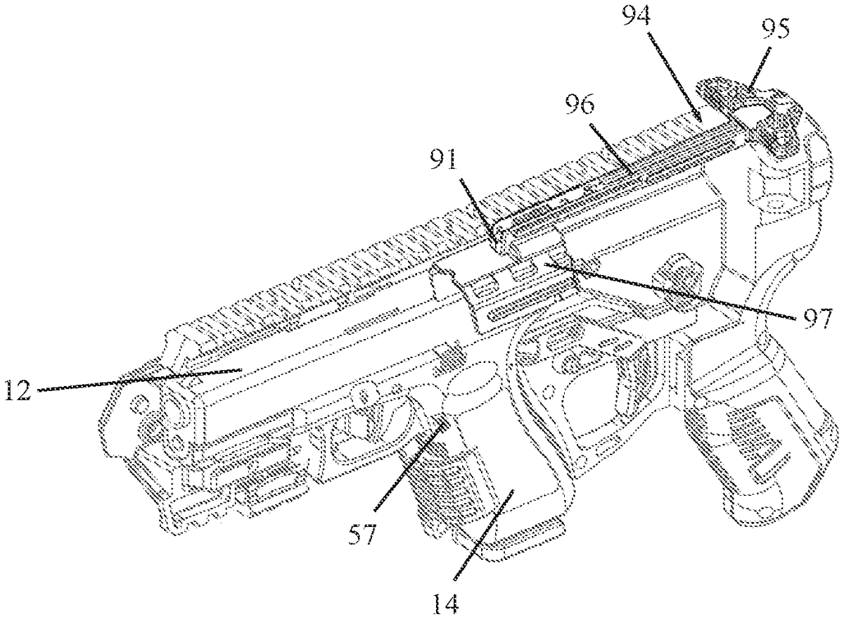
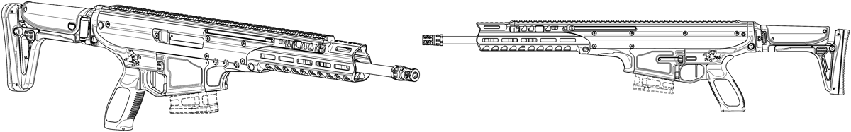
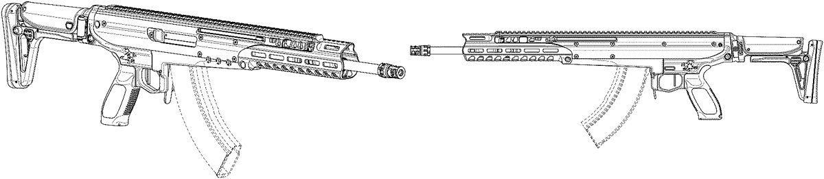
A pistol-to-rifle conversion kit includes a rifle body that includes a lower receiver, which includes a grip mounting portion, which is rearwardly adjacent to a trigger guard, which is rearwardly adjacent to a magazine well receiving portion, an auxiliary trigger sliding mounted in the rifle body and including an elongate member and a forward trigger interface member, which extends from a forward portion of the elongate member and which is configured to interface with a trigger of a pistol mounted in the rifle body, and a trigger member which extends from the elongate member for directly contacting a shooter's finger, and one or more of the following in any combination thereof: an ambidextrous rifle body quick-lock fastener, an ambidextrous magazine release button, an ambidextrous safety selector, and an assault-rifle-style charging handle.
Jan 6, 2026
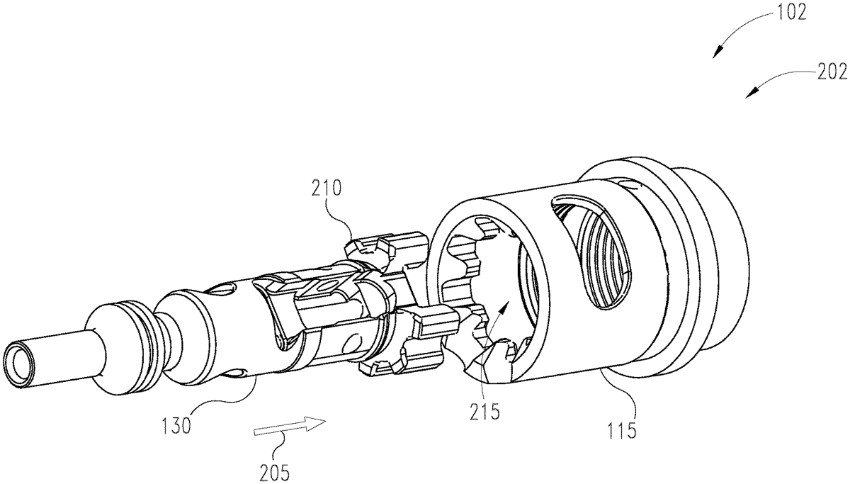
A barrel extension configured to reduce the likelihood of premature bolt failure in automatic and/or semi-automatic style weapons. The barrel extension includes one or more cutouts within a body of the barrel extension. The cutouts are configured to reduce rigidity of the barrel extension proximal to the location of the cutout. As the rigidity around the extractor is lowered, the force on the bolt lugs is more evenly distributed. In one example, the cutouts are in the form of a single oval cutout positioned adjacent an extractor of the bolt.
Jan 6, 2026
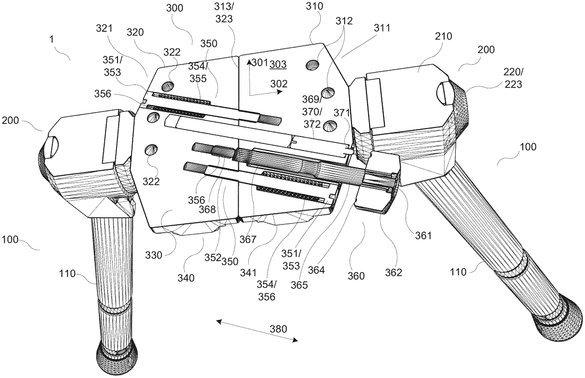
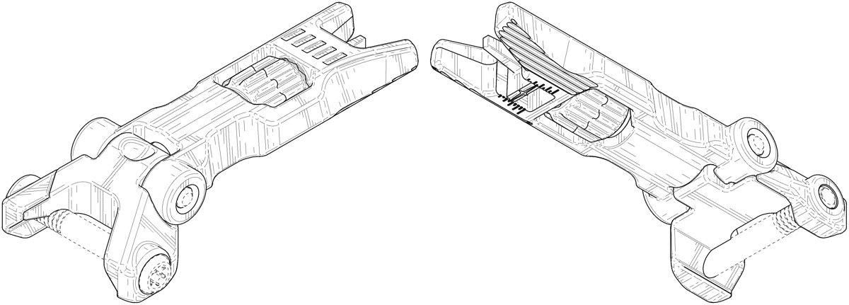
Interface connection adapter arrangement ( 300 ) for a bipod ( 1 ) for a rifle ( 2 ), wherein said arrangement further comprises a first part ( 310 ) and a second part ( 320 ), being trans-latable in relation to each other, the arrangement comprising a rifle fastener ( 331 ), in turn comprising cooperating fastener means both on said first part and on said second part; said rifle fastener being arranged to be activated for fastening the arrangement to the rifle by translating said first part in relation to said second part into a gripping position; and wherein the arrangement is arranged to be connected to two leg parts. The invention is characterised in that the arrangement further comprises a spring means ( 350 ), arranged to press the first part and the second part together; and a freedom of movement adjustment means ( 360 ), arranged to adjustably limit a freedom of translational movement of said first part in relation to said second part away from each other. The invention also relates to a method.
Jan 6, 2026
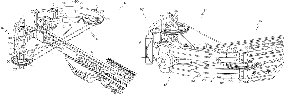
In some embodiments, an archery bow comprises a frame, a first limb assembly supporting a first rotatable member and a second limb assembly supporting a second rotatable member. The first rotatable member comprises a cam. A bowstring extends between the first rotatable member and the second rotatable member. A power cable is in communication with the cam. The first limb assembly has a width and a length, wherein the width is at least 26% of the length. In some embodiments, the width is at least 28% of the length.
Jan 6, 2026
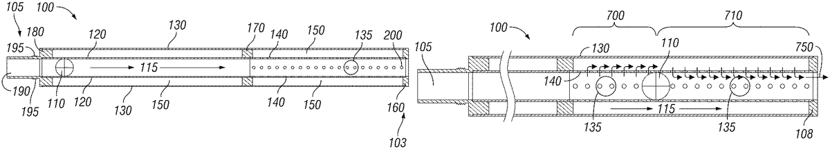
The present invention is a system and method pertaining to a Pneumatic Launcher Barrel Housing designed for enhanced noise suppression during projectile launching, maintaining shot accuracy and consistency, and allowing for greater customization and configurability. The system comprises an external layer, removable and replaceable internal layer(s), and air gap(s) between layers. The external layer facilitates attachment to existing projectile guns and provides a framework for securing internal layer(s), creating an air gap. The internal layer guides the paintball, utilizing expanding gases from the projectile gun to accelerate it through a stabilized path. This aids in dissipating residual air pressure and ensuring consistent shot trajectories.
Jan 6, 2026
A target dot sight includes a target illumination sensor that senses the amount of illumination at a target, rather than merely sensing the ambient sight of the entire operating environment. Then, based on the sensed target illumination, the target dot sight may automatically compensate for the brightness of the target.
Jan 6, 2026
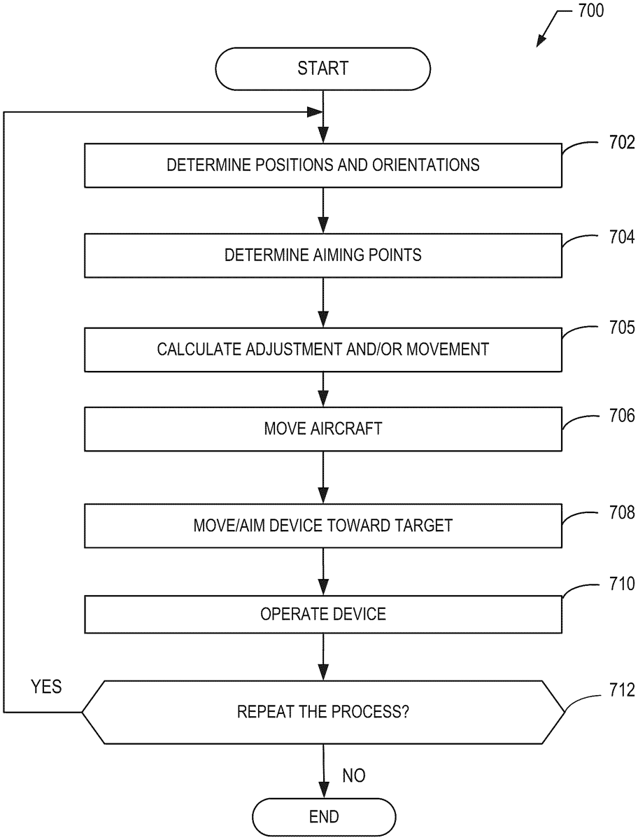
Methods and apparatus for pointing logic in aircraft are disclosed. A disclosed example apparatus to aim an aiming device carried by an aircraft includes at least one memory, machine readable instructions, and processor circuitry. The processor is to at least one of instantiate or execute the machine readable instructions to determine a position of a target, determine an orientation of the aircraft, determine aiming points based on the orientation and a movement range of the aiming device, and determine a movement of at least one of the aircraft or the aiming device based on the aiming points and the position to orient the aiming device toward the target.
Jan 6, 2026
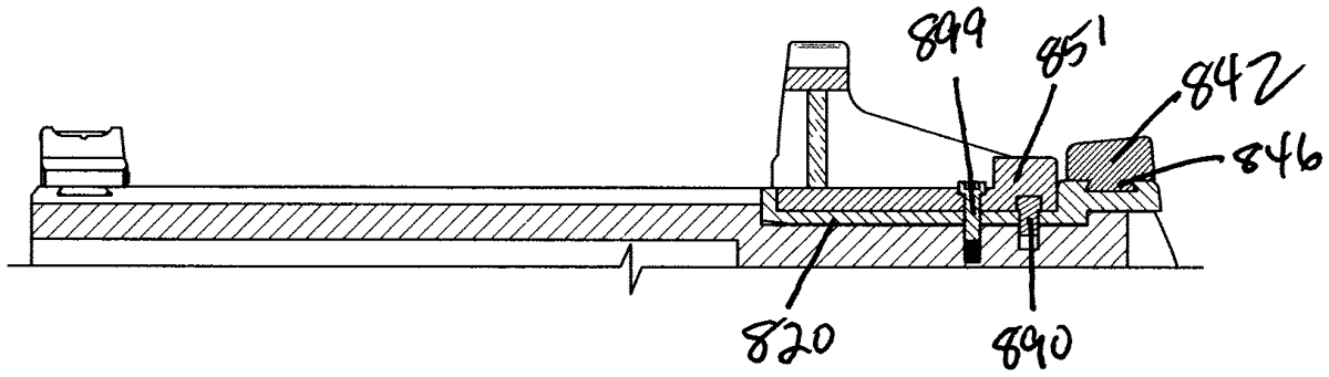
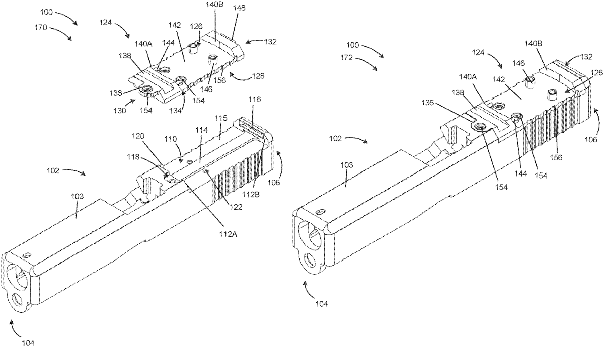
Sight systems comprise a sight receiver and a base attachable to and detachable from a sight receiver. A base carries a sighting component, such as an iron sight or optic sight. A sighting component may be attachably and detachably mounted to a base, or a sighting component may be made integrally with a base. A base may carry plural sighting components. Sight systems may include plural interchangeable sight receivers, bases, and/or sighting components. In some embodiments, interfitting structures at least partially restrain or retain a base and a sight receiver in longitudinal and lateral alignment, with such structures being longitudinally oriented. In some embodiments, interfitting structures at least partially restrain or retain a base and a sighting component in longitudinal alignment and lateral alignment, with such structures being longitudinally oriented. Some embodiments provide a fastener operable with a compatible and/or complementary surface, together used to urge interfitting parts together tightly.
Jan 6, 2026
Sight systems comprise a sight receiver and a base attachable to and detachable from a sight receiver. A base carries a sighting component, such as an iron sight or optic sight. A sighting component may be attachably and detachably mounted to a base, or a sighting component may be made integrally with a base. A base may carry plural sighting components. Sight systems may include plural interchangeable sight receivers, bases, and/or sighting components. In some embodiments, a sight system may comprise a base deployed with an elastomeric or otherwise resilient mounting pad. In some embodiments, an elastomeric or otherwise resilient mounting pad may be proud of a front or rear face of the base, or a side face of the base, or both. In some embodiments, the pad may be proud of a bottom surface of the base.
Jan 6, 2026
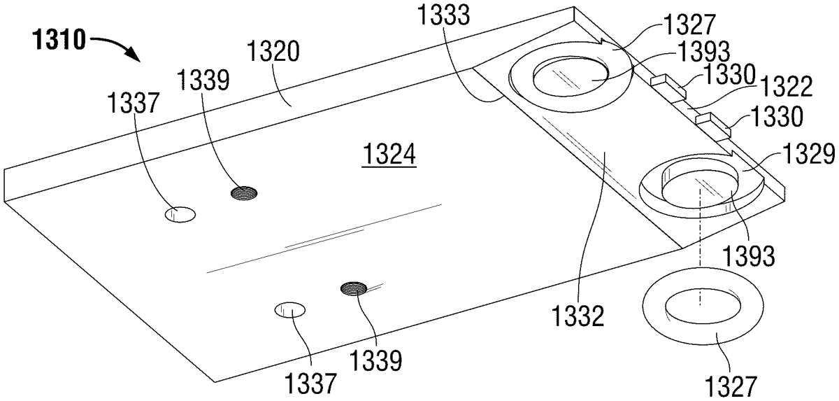
A firearm sight mounting plate assembly for a firearm is provided. The firearm sight mounting plate assembly includes a mounting plate. The mounting plate having a first area supporting an iron sight, and the mounting plate having a second area supporting an optic. The first area is different from the second area.
Jan 6, 2026
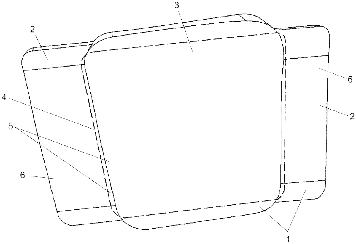
A combined armor plate is claimed. The combined armor plate is formed by soft and hard armor plates, the hard armor plate is arranged in a front part, the soft plate is arranged in a rear part. It comprises one or several hard armor plates having a total area smaller than a total area of the soft armor plate. The hard armor plates and the soft armor plate are interconnected such that they form firm and uniform structure in each formed hard ballistic part on each connection area between the soft armor plate and the hard armor plates. Soft ballistic parts have lower firmness and lower thickness of a ballistic material than the combined armor plate in locations of the hard ballistic parts. Technical effect: increasing effective ballistic protection area and resistance of the hard armor plate and the soft armor plate to penetration and blunt trauma effect.
Jan 6, 2026
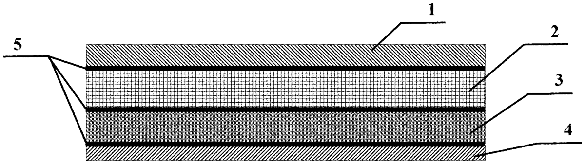
A lightweight, ballistic and blast-resistant multi-phase composite armor material based on a high-toughness heterogeneous interfacial layer, including a crack-arresting layer, a bullet-breaking layer, an energy-absorbing layer, and a support layer. The crack-arresting layer, the bullet-breaking layer, the energy-absorbing layer, and the support layer are stacked in sequence from a bullet-accepting side to the inside. Adjacent two layers are bonded with an adhesive film layer. The crack-arresting layer and the support layer are both made of a carbon fiber composite. The bullet-breaking layer is made of ceramic. The energy-absorbing layer is made of an ultra-high molecular weight polyethylene fiber composite. The adhesive film layer is made of a high-toughness heterogeneous interfacial adhesive.
Jan 6, 2026
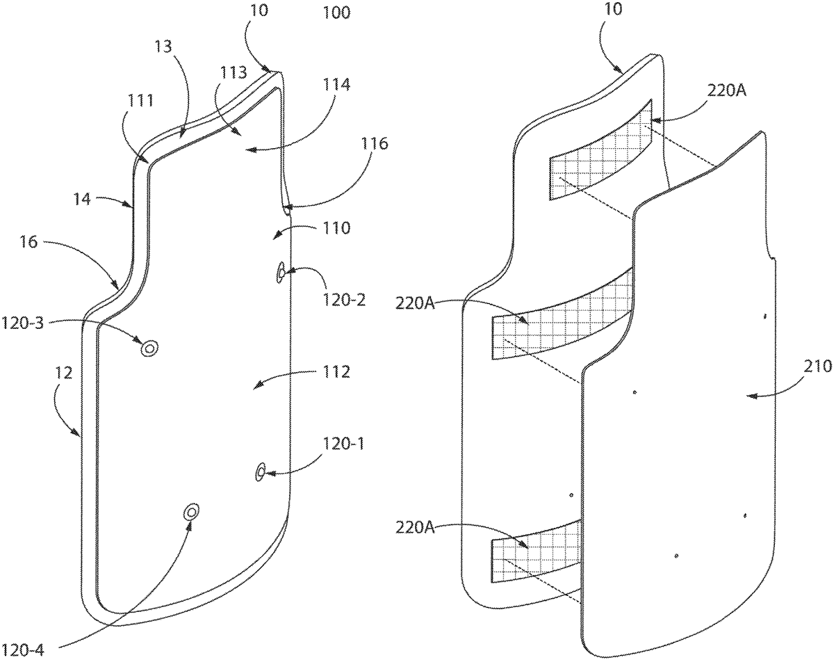
In various embodiments, a ballistic shield system may comprise a shield, a ballistic cover, and a fastening system. The shield may have a first curved profile and a first ballistic rating. The ballistic cover may have a second curved profile and a second ballistic rating. The fastening system may be configured to attach the ballistic cover to the shield. Moreover, the second curved profile may match the first curved profile.
Jan 6, 2026
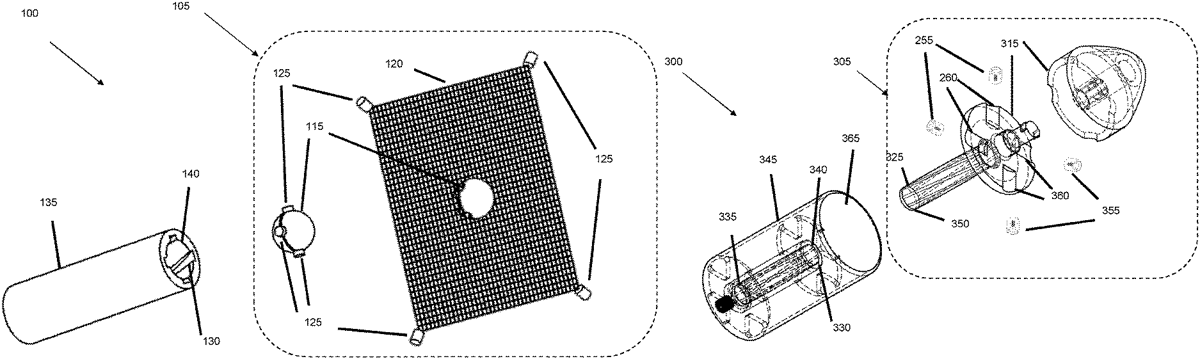
An assembly for use as a net-launching projectile is disclosed. The assembly comprises a housing storing a net in a packed configuration and configured such that a rotation of the assembly causes the net to be ejected from the housing, thereby unpacking the net into an expanded configuration. The assembly also comprises a plurality of circumferentially disposed protrusions or ridges for engaging with corresponding rifling in a barrel to induce the rotation of the assembly when launched. Also disclosed is a net-launching system and a method of capturing an aerial target.
Jan 6, 2026
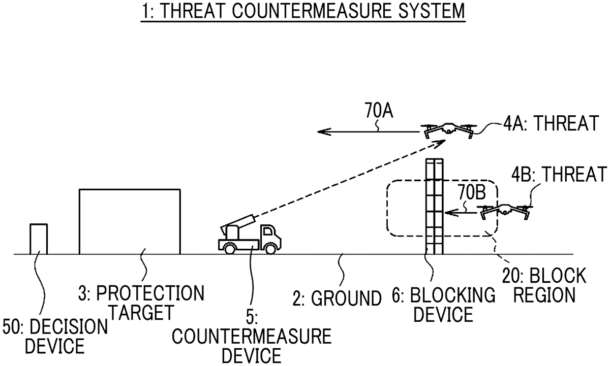
Provided are a threat-countering system and a threat-countering method for efficiently countering incoming threats by using laser irradiation. The threat-countering system comprises a countering device, a deterrent device, and a decision device. The countering device detects incoming threats and counters the threats by using laser irradiation. The deterrent device is installed to prevent threats from approaching a protected object through a deterrent region in which the power of the laser irradiation is assumed to be lower than a predetermined threshold. The decision device decides the position of the upper end of the deterrent device on the basis of the upper end of the deterrent region.
Jan 6, 2026
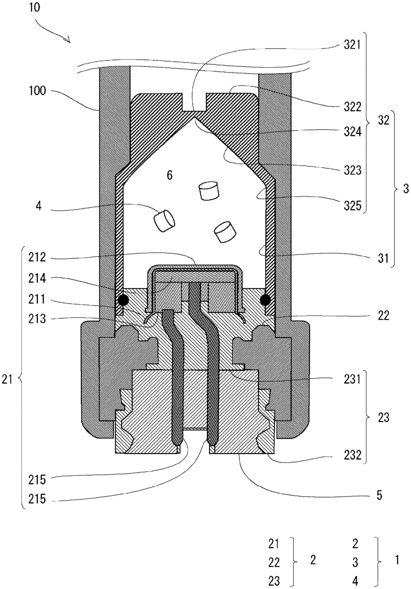
A gas generator includes an ignition device including an igniter, an igniter holding portion, and a fixing portion made of resin and a case having a bottomed tubular shape and being configured to accommodate a gas generating agent which combusts by actuation of the ignition device, the case made of resin and including a side wall portion with a base end side being connected to the fixing portion, and a closing end portion configured to close a tip end side. The closing end portion includes a fragile part configured to open by a combustion product generated by the gas generating agent, a periphery of the fragile part is greater in thickness than the fragile part, and an annular inclination portion is formed inside the case from a predetermined position of the side wall portion to the fragile part.
Jan 6, 2026
The invention discloses an expandable bullet having a set of deformable petals each including a main and set of two small petals, with the petals formed by a pattern of slits across a hollow core of the bullet tip.
Jan 6, 2026
A nosepiece is provided with a recess or cup shape with internal dimensions that provides cavity suppression of a body entering an air and water interface. The nosepiece includes a circular portion with a diameter connectable to a nose of the body. The circular portion has a cylindrical first section and a cylindrical second section with the recess as the formed cup in the first section at a depth where the diameter and depth are selected based on a Weber number for the body such that a cavity is suppressed as the nosepiece and the body enter the air and water interface.
Jan 6, 2026
A bullet cartridge ( 1 ) may include a bullet case ( 3 ) defining a caliber diameter (D), a projectile ( 4 ) inserted into the neck portion ( 31 ) of the bullet case ( 3 ), and at least one annular layer ( 51, 52 ) of a sealing medium ( 5 ) formed from a sealing medium ( 5 ) between the bullet case ( 3 ) and the projectile ( 4 ). The bullet case ( 3 ) may be provided with the annular layer ( 51, 52 ) using a microdosing device (microdoser) ( 7 ). The annular layer may include not more than 1 mg of sealing medium ( 5 ) per mm of caliber diameter (D).
Jan 6, 2026
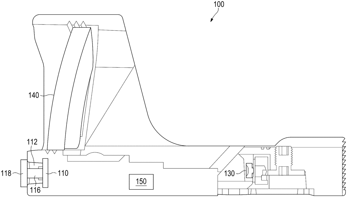
An optic assembly may include: an environmentally isolated cavity defined by at least a front lens and a housing; a light source located inside the environmentally isolated cavity, the light source to project a reticle on the front lens; and a carrier assembly located inside the environmentally isolated cavity, wherein the light source is mounted on a carrier of the carrier assembly, and the carrier assembly includes: at least one boss fixably located with respect to a bottom interior surface of the environmentally isolated cavity; and a carrier lift slidingly movable along the at least one boss to raise or lower the light source relative to the front lens; wherein the carrier is slidably movable relative to the carrier lift to laterally adjust a position of the light source relative to the front lens. Other embodiments may be disclosed and/or claimed.
Jan 6, 2026
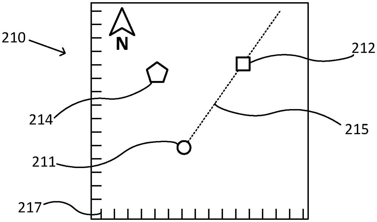
A method for determining a direction at a position is provided. The method involves obtaining an orthorectified photo of a region of Earth's surface comprising the position, and a coordinate system for the orthorectified photo; identifying the position in the orthorectified photo; identifying a reference object in the orthorectified photo; determining a reference direction between the position and the identified reference object; capturing at least one digital photo at the position with a calibrated digital camera, wherein at least one of the at least one captured digital photo depicts the reference object; and determining the direction based on the at least one captured digital photo and the determined reference direction, wherein the determined direction is based on at least one pixel coordinate corresponding to the depicted reference object in the at least one captured digital photo depicting the reference object.
Jan 6, 2026
Jan 6, 2026
Jan 6, 2026